42. sequential circuits [diagram] d flip flop logic diagram (a) electronic implementation of a jk-latch which is a sequential
LogicBlocks Experiment Guide - SparkFun Learn
Jk latch multisim
Free images
Electronic latch circuit diagramSolved 4. prove the circuit below (consisting of a j-k latch Jk latch truth table circuit experiment guide sparkfun learn logic something looks likeLatch logic ladder circuitlab.
Jk flip flop diagram and truth tableLatch using jk flip flop Latch jk digital world gif asic(a) electronic implementation of a jk-latch which is a sequential.

Rs flip flop circuit diagram
Circuito de retención del transistor: ¿para qué sirve el condensadorFlop latch logic flops temporizador circuits circuiti digitali flipflop How to make a transistor latch circuit – homemade circuit projectsHow to wire a latching lighting contactor in series.
Inside intel's first product: the 3101 ram chip held just 64 bits¿diagrama de compuerta lógica para jk latch? (no flip-flop) Latch transistor forcingJk flip flop diagram and truth table.
Jk latch gated circuit flip flop electronics experiment diagram digital enable alpha
F-alpha.net: experiment 26Jk flip-flop explained Latch circuit electronics gate schematic reset active input high dummies low output basics set nor when inputsJk latch circuit diagram.
Jk latch circuit diagramSr latch circuit schematic J k flip flop explained in detailSimple latch circuit 'ladder logic'.

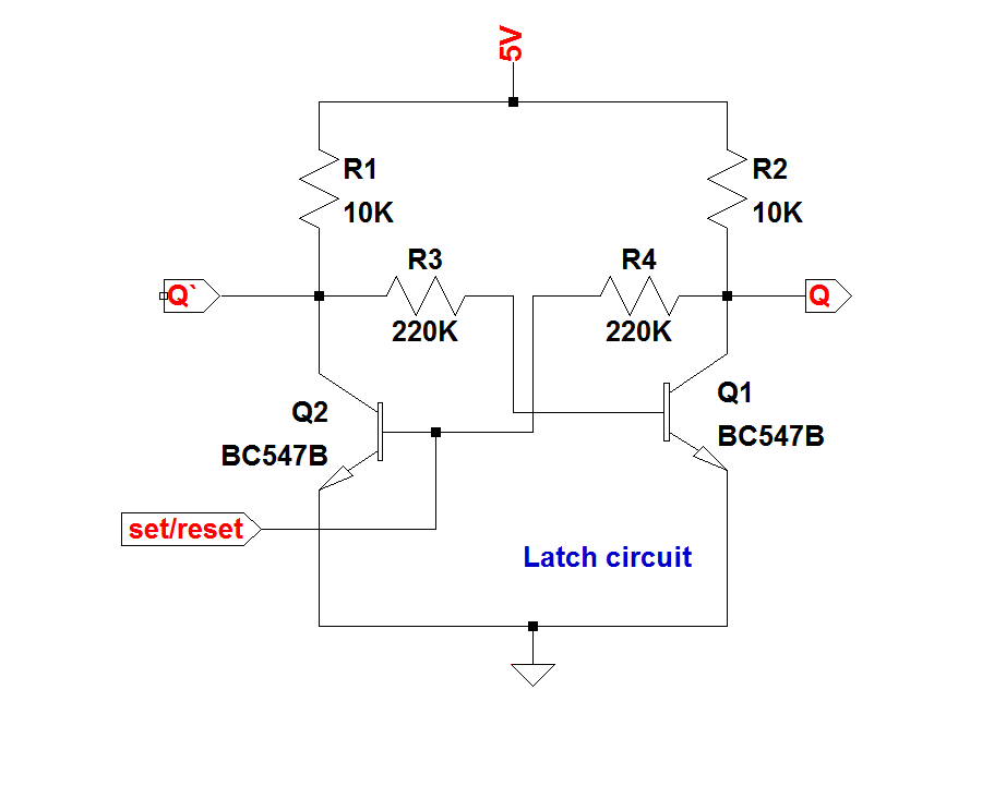
Latch circuit transistor simple diagram transistors engineering explanation
Jk latch flop circuitWhat is a latch ??? (theory & making of latch using transistors) Logicblocks experiment guideUniversity of maryland baltimore county department of computer science.
Circuits with latches in digital electronicsTemporizador digital Latch jkJk latch table truth solved circuit wired following answer problem been has.

Latch transistor transistors simple circuit circuits using use two useful diagram homemade explained electronics couple make electronic input board trigger
Solved the jk latch is wired as the following: a b nor referElectronics basics: what is a latch circuit D latch flip flop circuit diagramLatch jk.
.


